Building blocks for 3D printing: Aibuild’s component-based slicing approach

13 May 2021
Author: Leonidas Leonidou

The way most 3D printing slicing software are experienced by their users can be described as a black box. The usual workflow begins with the users loading their CAD model into the software, entering the desired values for a number of inputs, giving the instruction to the software to slice the model, and finally the software returns the sliced geometry. This process is linear and there is no way to modify the sliced output or fine-tune it. If any changes are required, the only option for the user is to go back to the list of input parameters, modify some values and slice the model from the beginning. If the output is still not as expected, this feedback loop between the sliced model and the values of the input parameters is repeated until the user gets the desired result.

While this workflow offers the advantage of being able to slice a model with minimum effort and technical expertise, its flaws start to show in cases where the user requires increased control over the slicing process. In more advanced workflows, experienced users often try to find ways to hack the software in order to fine-tune the outputs to match the desired output. This means that they have to keep going back to the CAD software and modify the original geometry, export it, load it in the slicer software and slice it again. However, it is more often than not that this design fine-tuning becomes a very lengthy and tedious process that in cases of designing for production it can span weeks of design iterations and sometimes the final output is still not 100% as expected.

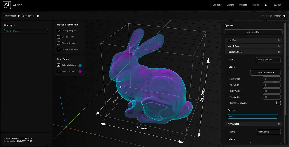
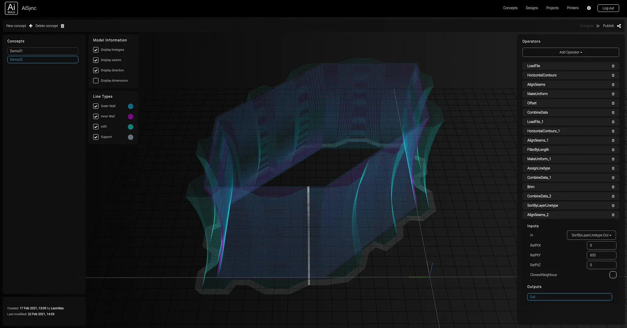
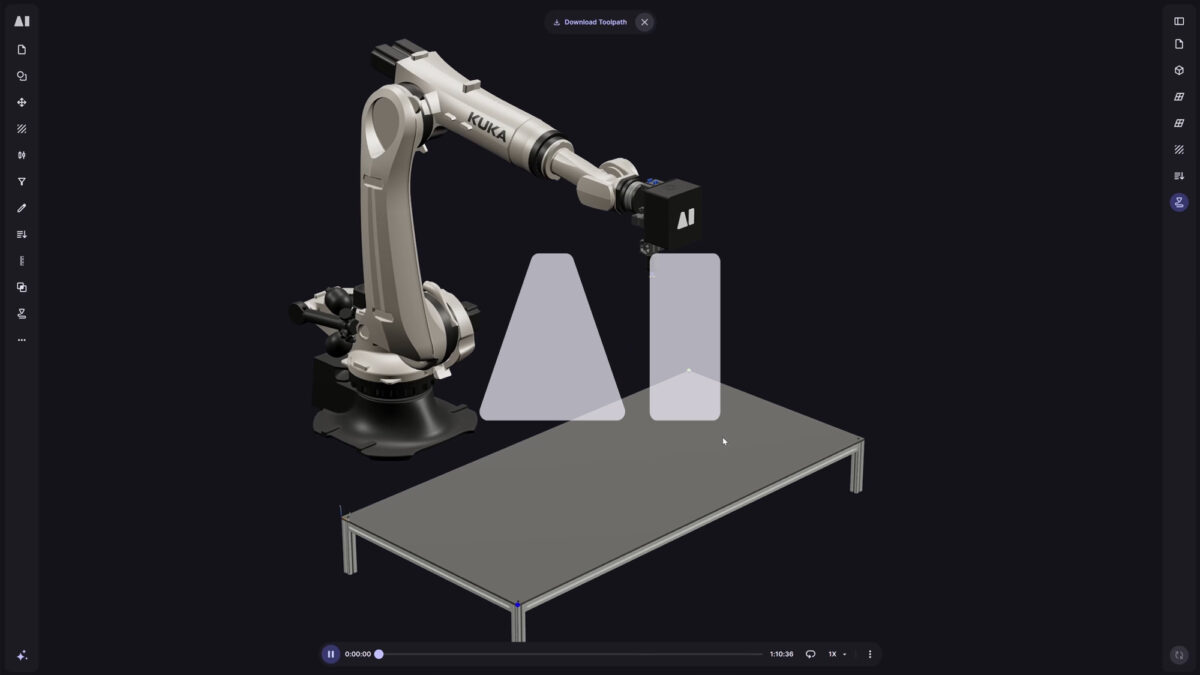
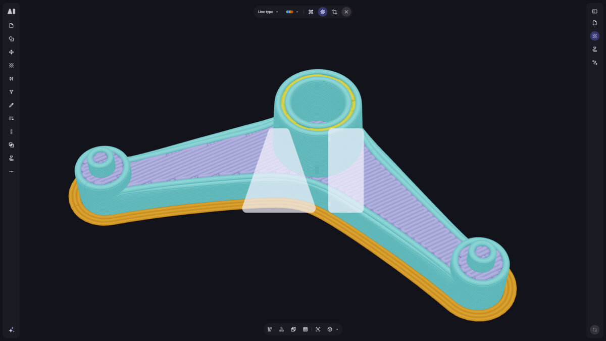
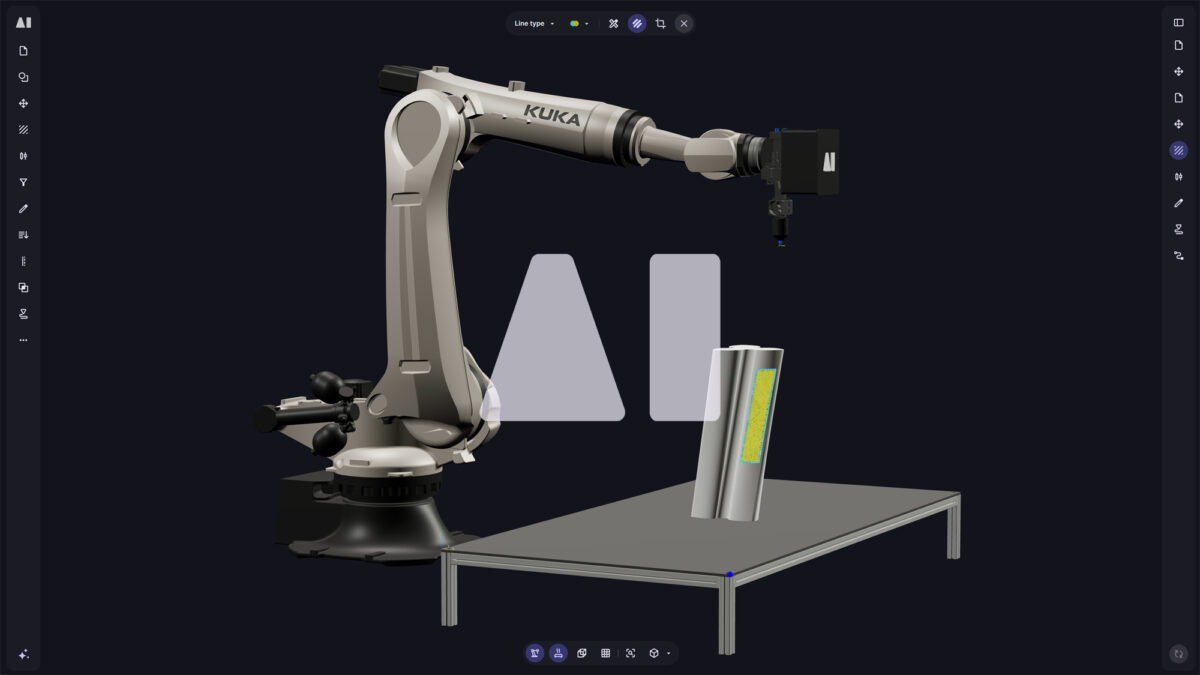
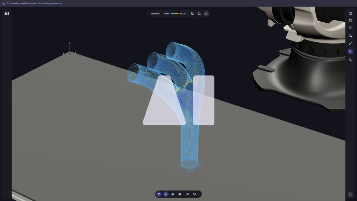
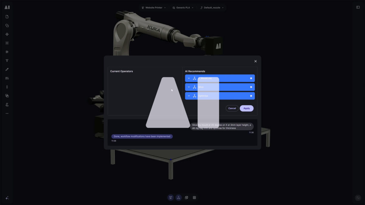
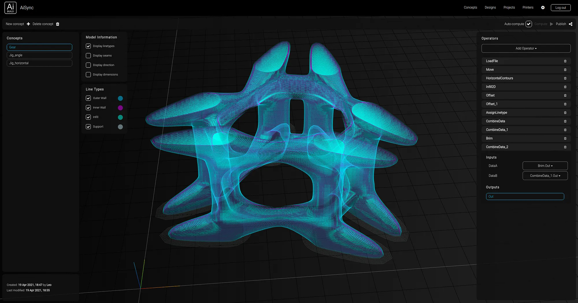
As an alternative to this black box approach, AiSync, Ai Build’s cloud-based platform for large-scale additive manufacturing, handles toolpath generation in a more flexible approach through component-based slicing. Users get access to a powerful engine of components called operators that perform geometric or analytical operations and allow the development of custom workflows based on specific design needs. These workflows are parametric in a form of visual programming with stackable modules for building truly customisable solutions, so they can be easily modified or reused for different designs with similar requirements.

By using this approach, the workflow is not predefined anymore through a fixed amount of inputs and outputs, but the user has the freedom to build their own tools from the bottom-up for each project to best suit the project needs.

Stanford bunny sliced horizontally through a combination of operators

Each workflow begins as an empty canvas. The user can then add operators to this workflow from a long list of available operations to achieve the desired output.

Each operator has a number of inputs and outputs, and the stackable logic means that the output of an operator becomes the input of another operator. Data keeps getting exchanged between operators and modified until the final result is reached.

A closer look at the 2 operators used in the example above.

The image above shows a simple example where a 3D model has been uploaded on the platform and sliced horizontally using a number of operators. Looking at the steps involved (image on the left), the user first creates a ‘Load File’ operator in which a design is selected as input from the organisation’s design library. The output of this operator then becomes the input of the high-level ‘Horizontal Slicer’ operator in which a number of parameters such as layer height, line thickness and number of walls are defined and the output is the sliced geometry organised as a list of contours. The user then has the option to publish the output of this operator to their design library and proceed by generating a toolpath from that design, or they can keep stacking operators and modifying the geometry further.

The example above shows a simple workflow for horizontal slicing, but the areas where the advantages of component-based slicing shine are in industry-specific applications that have clear and strict specifications, making control an uppermost requirement. In order to showcase this better, two case studies related to the construction and automotive/aerospace industries are presented in the following sections.

Industry case study: Molds for construction

The presented case study is a 3D-printed mold for casting concrete that would be milled down afterwards so that a smooth finish is achieved. The two main requirements were the production of a piece that has a clean surface finish for casting and a sturdy structure that can withstand the applied forces. For this, the following had to be achieved:

  • Double wall for additional strength and an external structural layer
  • The main surface is printed thicker for increased strength and to compensate for the material that will be subtracted during the milling process
  • Continuous toolpath with minimum travel distance to prevent any printing artefacts
  • Control over the line sequence to ensure clean and uniform finish in the surface that would be used for casting
Right: mold surface to be used for casting concrete. Left: External structure to be printed around the surface

The developed workflow included the following key steps:

The geometry was organised in different linetypes. Organising the geometry into the correct linetypes was a key step in the process. This allowed control over the line sequence, as the contours were sorted based on their linetypes, and this meant that the inner surface could always be printed first and then move outwards on each layer. Moreover, different linetypes can be assigned different printing speed, so it is easy to print some sections thicker than others (in this case the main surface that would be milled after printing).

The seams were aligned based on a reference point. An operator for aligning seams was used for this step, in which the user enters a reference point so that the closest point on the contour from the reference point becomes the new seam. The next contour on the list would find its closest point on the seam of the previous line and update it, until all contours have been updated. This allowed a continuous toolpath as all the seams became aligned, which meant that there was no travel movement from the printer but the extrusion was uninterrupted.

Additional walls were created by offsetting the inner wall contours. This operation allowed to use the base contour geometry as the guide for generating additional walls at the user-specified distance from the main walls, so that extra strength could be achieved.

A brim was generated for better adhesion on the printing bed. For this operation a brim operator was used in which the outer structure model was used as the guide to get the shape’s outline on the base layer and produce a number of offset contours at the specified distance as a brim.

The final result as shown below was generated in just a few minutes and it managed to fulfil all the requirements for this model, proving that time-consuming design iterations and constant transitions between design and slicing software are unnecessary when using AiSync’s component based slicing.

Final sliced mold geometry through the combination of a number of operators

Industry case study: Jigs for aerospace and automotive

Another application that is very common in the aerospace and automotive industries is that of tooling, and specifically jigs. In the following example we explore how a jig for carbon fiber layup can be easily sliced in an optimised way through the use of a few operators for production.

One of the main requirements for this project was the surface tolerance to be as low as possible and with a consistent finish. Moreover, minimising printing time and material use were also important factors as the fast pace of innovation in these industries requires constant innovation and fast prototyping.

The main problem that would arise when using a conventional slicing software for this project is that when orientated vertically on the printing bed, the print would most probably collapse during printing because of its big length in relation to the small surface area touching the printing bed. If on the other hand the model was placed horizontally as shown below, then it would require large amount of support structure that would in turn lead to great increase in printing time and material cost.

An alternative solution was to make use of the non-horizontal slicing operators of AiSync that allow slicing a model at an angular or multi-planar direction, or even using non-planar guides. In the case of this model an angular slicing method was used where the horizontal plane was rotated at 45 degrees around the world x axis. The result is a set of contours that can be printed by a multi-axis printer such as a robotic arm without the need of any support, as shown in the bottom image.

A brim was also added to enable better bed adhesion, while the seams of the contours were aligned and modified to have uniform direction, enabling a consistent surface finish, continuous toolpath and minimum possible printing time and material cost.

Right: 3D model of jig to be sliced.Left: Sliced jig at an angle of 45 degrees.
Close-up of the sliced jig at an angle. It can be seen that each layer is supported by the previous layer.

Advantages of the component-based approach

The first words that come to mind when thinking of the advantages of this slicing approach over the conventional black-box approach of slicing software is flexibilitycustomisation and control.

The predetermined structures of conventional slicers give way for a more fluid workflow, as the user is able to fine-tune the output by changing specific components. At the same time, beginning with an empty canvas allows for truly customised solutions based on the special requirements of each project, which can be developed through the combination of different operators. Finally, it is up to the user to decide how much control they require over the slicing process, as they are able to either use high-level operators for fast slicing, or start building from the bottom-up and control every aspect of the slicing process.

In addition, the software allows the combination of different operators for creating a custom operator in order to make reusability easy without having to spend too much time every time building the same solutions.

In this way, the user can steadily build their own arsenal of custom operators that best suit their projects and reoccurring problems and customise the software according to their needs.

With the number of innovative applications in large scale 3D printing increasing constantly, AiSync’s component-based slicing approach gives designers and technicians a much bigger level of control in the fabrication process and makes innovation much easier.

Being developed around the needs of specific industries such as construction, automotive, aerospace, marine and energy, the platform’s operators are a powerful tool that can elevate and expedite production from design to manufacturing. For more information and a demonstration of AiSync’s capabilities get in touch.