Optimising print temperature with Airtech

26 June 2024
Author: Jack Sandiford

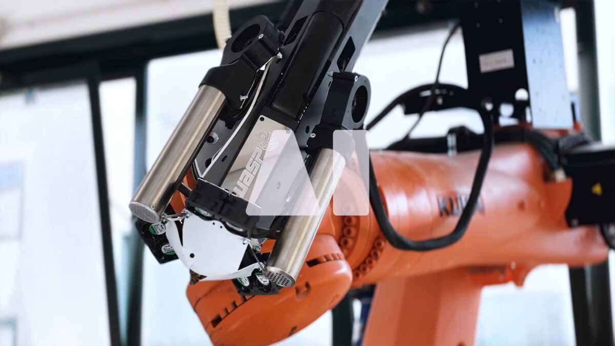
Successful outcomes in large format AM require synergy between software, hardware and materials. With regard to the latter, having a deep understanding of material properties and behaviours is essential, which is why we work closely with leading AM material manufacturers like @Airtech. Understanding those properties is good, automating access to those properties is even better.

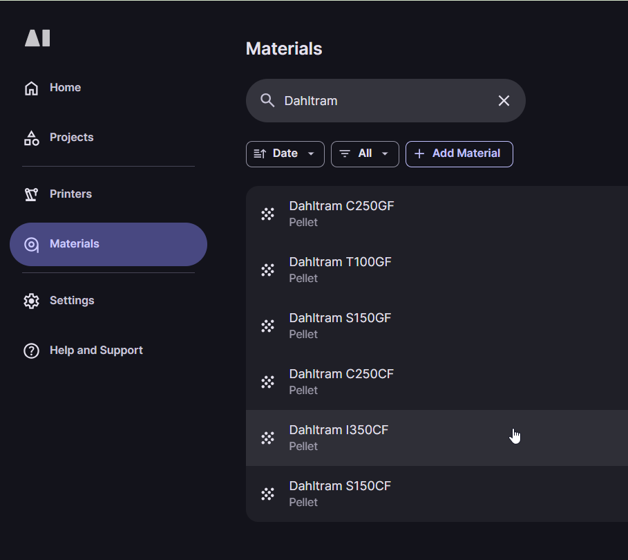
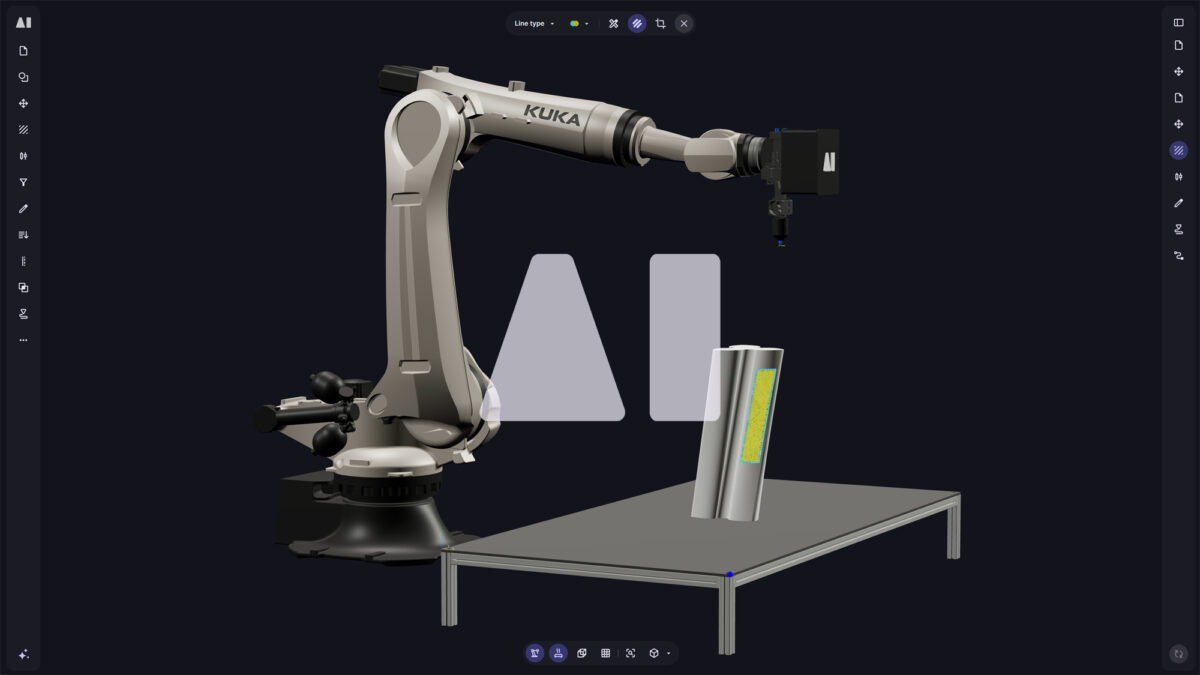
This led us to introduce our Material Library into our software, the home for all your 3D printing material parameters.

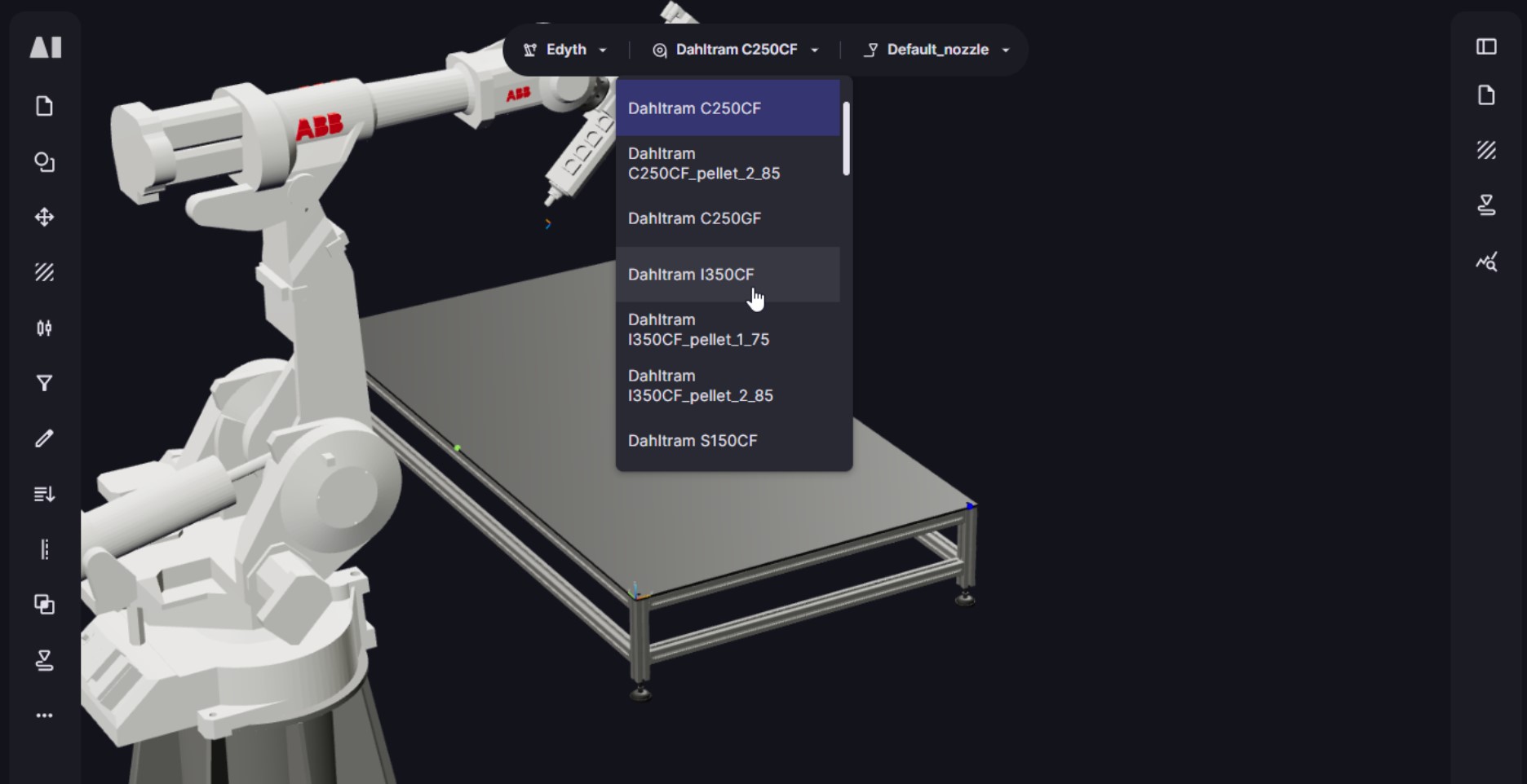
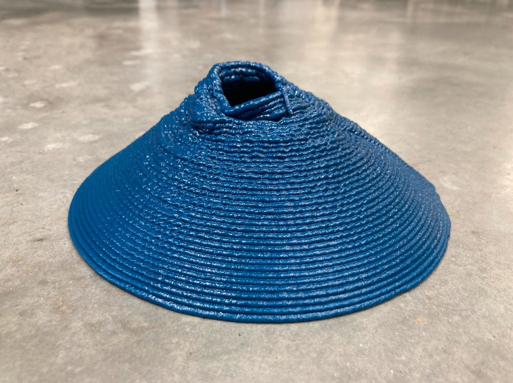
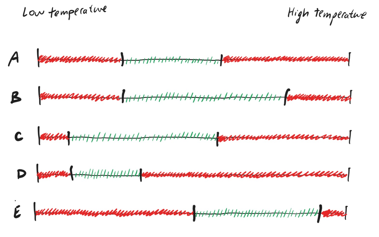
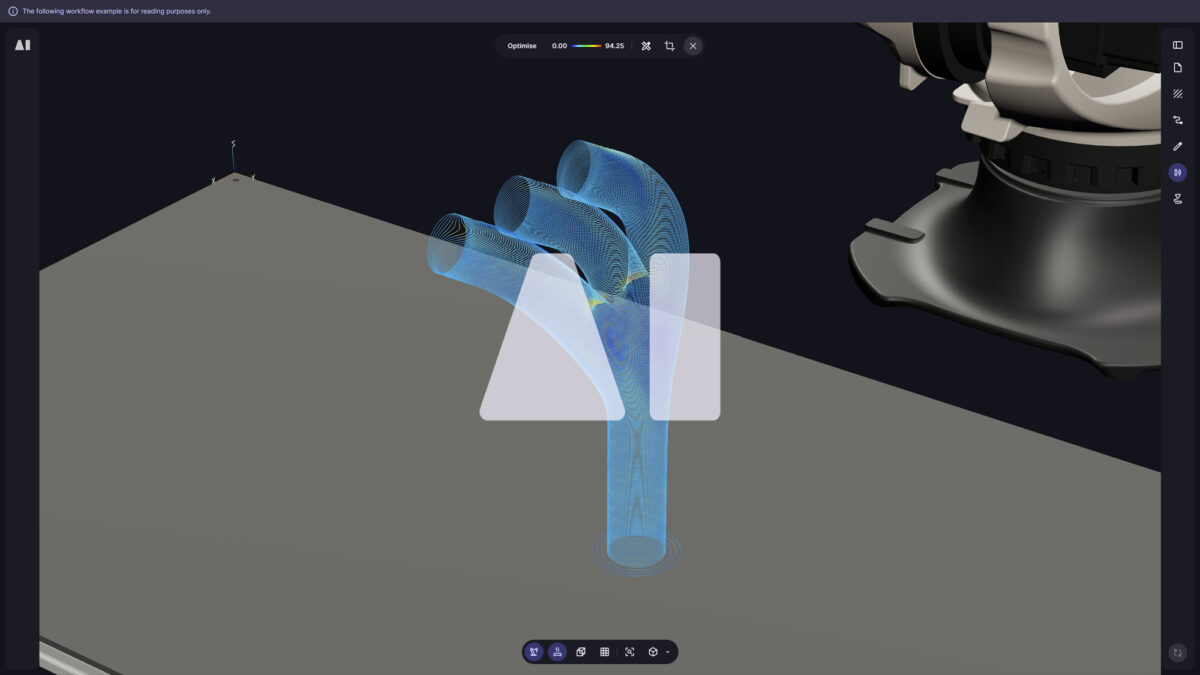
From generic PLA for prototyping, to @Airtech high-performing Dahltram® I-350CF for composite moulds and tools, to Nickel 718, all polymer and metal printing parameters are now stored in one place, ready to be used in your workflows. Our engineering team is testing new materials everyday with physical performance checks. This rigorous testing gives us fine-tuned process parameters, ensuring you can achieve peak AM performance for every material. (Read on for an example.)

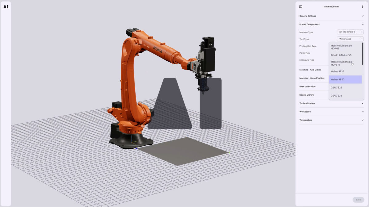
The new Aibuild Material Library replaces manually adjusting values after every print with an automatic optimum value and regular updates for new materials as they come onto the market. Parameters such as; printing temperature, cooling time, toolpath settings and more, all precisely calibrated to your selected material and nozzle. With customizable material cards, you can add, edit and clone to manage materials to suit your application and your organisation’s unique needs.

This is one of our many steps towards helping manufacturers to realise peak efficiency, quality and accessibility in large format 3D printing.

Example: Choosing the right material for your print.

Let’s 3D print a part.

Open Aibuild software and create a new workflow.

The first step is to select your printer, nozzle and material. You can change these later.

By doing this, you can ensure the toolpath you generate is printable, doesn’t lead to a collision, and uses the optimum settings for your configuration.

Next, we will build the workflow.

Like how a toolpath contains the instructions to print a part, and a workflow contains the instructions to make a toolpath. You can add to, edit and optimise your workflow to improve your print.

To print a part, the basic recipe is Load, Slice, Toolpath. Let’s add these to our workflow.

Hit Compute. Your toolpath is ready! 

Let’s print our part.

Unfortunately, this print has failed. It has sagged during the print and the layers have deformed.

Why? What can we do about this? 

Controlling thermal effects is key to achieving good print quality in AM, especially for large-format.

In large-format AM, because the parts are a lot larger, it is necessary to use a larger deposition rate (kilogram per hour) to reduce excessive print times. This means printing a thicker line of extruded material (the bead). In polymers, this results in thermal build up in the core of the bead due to the poor thermal conductivity of the polymer and the higher volume to surface area ratio.

Excess heat will cause the polymer to exhibit thermo-mechanical behaviour such as deformation, also known as ‘sagging’. If this effect is repeated layer after layer, the print will deform significantly from the intended shape. How do we avoid this? How can we reduce thermal build up?

There are a few ways to counter this problem.

  1. Allow for cooling time 
  2. Use a material that doesn’t deform at high temperatures
  3. Use a narrower bead

However – if the previous layer temperature is too low, this can also present issues. Poor bed adhesion, poor interlayer bonding and low overall strength are due to low temperatures where material bonding is low.

Each material has a temperature window for optimum printing. 

This is the key to printing fast without compromising your print quality.

How can we print within this temperature range?

I see a temperature distribution of the predicted layer temperatures as well as a per-layer check if the layer temperature is outside the permissible range.

All of the layers are red. This means that every layer has a temperature outside of the recommended temperature range for this material. Thermo-mechanical effects will cause the material to ‘sag’ which will lead to a failed build.

Let’s try our first strategy to improve this: allow cooling time.

Enable “Layer Time Management” in the Toolpath operator and choose an option to introduce cooling time.

We can choose to add a wait time after each layer, to adapt the layer print time by a fixed amount of time, or to adapt the speed based on the results of the thermal simulation.

We will adapt the speed based on the thermal simulation. This will reduce the speed of the robot and the deposition so that there is enough time for cooling for each layer to avoid the sagging, without slowing our print down too much so that our overall print time becomes excessive.

Now let’s re-run the layer thermal analysis.

Now we can see only the bottom of our print is outside the temperature window.

There is a bottom limit of the speed optimisation. We can reduce the speed further to allow for more cooling time with the “Optimisation min speed limit” parameter.

Instead of reducing the speed of our print even more, which will lead to a lengthy print process, let’s find another material.

I want to find a material that can be printed at high nozzle temperatures with less cooling time.

We can browse the materials library to find a more suitable material.

Let’s look at Airtech’s high-performing Dahltram® polymer materials.

The important parameter for thermal build up is minimum and maximum previous layer temperature. This is the lower and upper limit for our material’s temperature window. We want to find a material that has a higher maximum previous layer temperature because this will allow us to print faster, without the need for as much cooling time.

Of these three materials above, the Airtech Dahltram® I-350CF has the highest temperature window.

Let’s set our print material to this.

Now, let’s re-run enable adaptive speed in the Toolpath operator and check the results of the thermal simulation. 

Every layer is now green, indicating that the print temperature is predicted to be within the suitable temperature range for this material.

Great!

I can download the toolpath, send it to the machine and print my part without wasting material.

With thermal simulation, you can adapt printing speed to optimise cooling and print time to your liking. This allows you to achieve high print quality without sacrificing hours of print time unnecessarily.

Why Aibuild?

With a connected product lifecycle, data is more easily shared and traceable between teams, keeping them synced with each other. Why waste time with trial-and-error prints and studying optimum parameters when you can have that data at your fingertips?

Connect materials, hardware, software: Bring your printers, hardware, files and processes under one roof. Switch between materials, printers and files to assess cost, weight and print time. 

Build a recipe: Package your process into a recipe that can be used time-and-again. Hide settings that should remain fixed, and expose settings such as layer height, wall thickness and input file.

Leverage the best of additive in Aibuild 2.0, your manufacturing hub for AM.