Stop gambling with interpass temperature – Here's how to predict and control every layer

16 July 2025
Author: Guy Brown

Heat management shouldn’t be a roll of the dice.

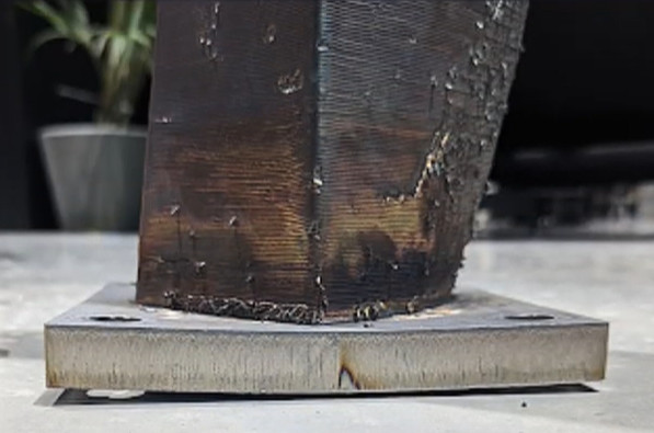
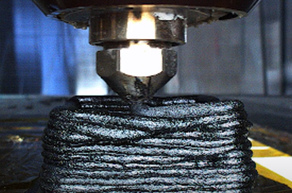
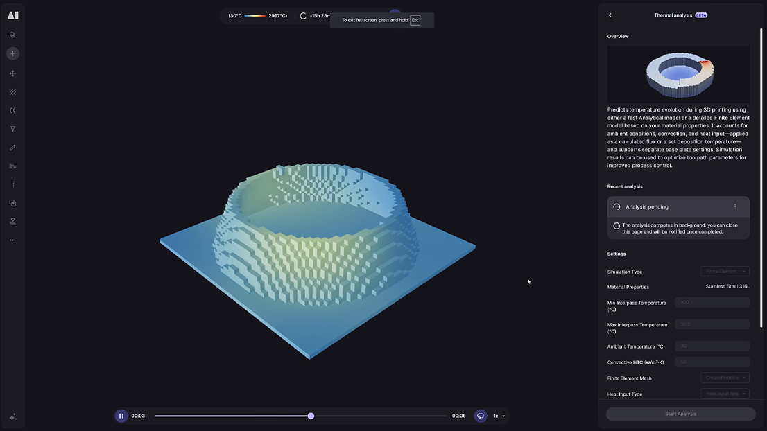
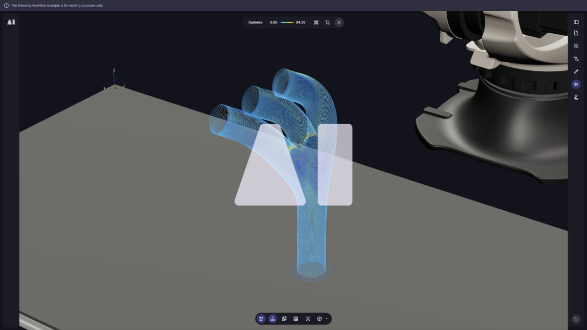
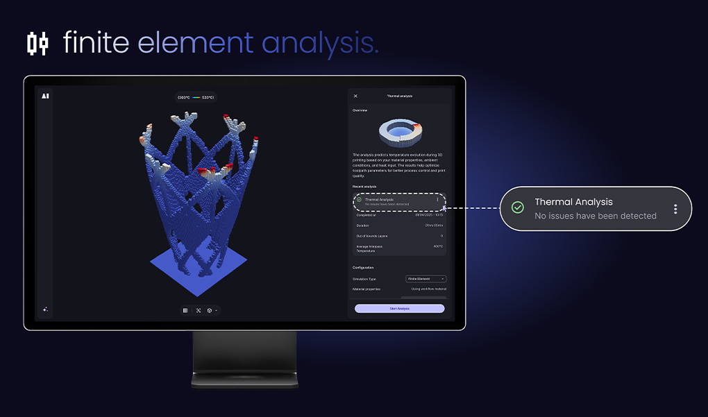
If you have ever watched a 20-hour large-format additive build slump into a shiny puddle or fracture on the very next layer, you already know the villain: uncontrolled heat. In metal and polymer LFAM, interpass temperature rules everything. Too hot, the bead sags; too cold, it cracks – and either way the mechanical properties suffer. Our team has spent the past 6 months turning that pain point into a predictable, GPU-accelerated workflow, and today we’re beta releasing the industry’s first finite-element (FE) thermal simulator baked directly into a CAM toolpathing engine.

Why thermal management still holds back LFAM.


Thermal behaviour in large beads is brutally non-linear: conduction into underlying material, convection to the surrounding air, radiation off a glowing surface – all of it changes every second. Each material has a narrow “process window” of safe interpass temperatures, but that window is easy to overshoot:

> Target Interpass Temperature: out of tolerance and surface defects

< Target Interpass Temperature: inter-layer cracks, loss of tensile strength

Variable cooling-rate alloys: micro-structure drifts off-spec, compromising certifiability.

The conclusion? You either manage heat proactively or accept scrap risk.

Monitor-and-control vs. simulate-and-optimise.


Real-time thermography (monitor-and-control) is fantastic for pass/fail validation, but it is limited in the types of thermal control you can do (mostly just dynamic waits between layers). Simulation during toolpathing lets you change the build order, speed, waits and parameters before pressing Print.


Approach Strength Limitation
Monitor &
control
 

High accuracy, essential for certification


Corrective behaviour is limited


Simulate & optimise Deep optimisation of printing order and parameters Needs a fast, reliable model

Ultimately, the combination of both approaches unlocks the most benefit as it enables the accuracy of the monitor & control approach (by calibrating and validating the simulation prediction), whilst having the offline optimisation flexibility of a predictive simulation approach.

From analytical to finite-element – the evolution.


Our first-generation analytical solver was built for speed—it could sketch a temperature envelope in the time it takes to make coffee. The catch was its simplifying assumptions: a low-conductivity world where conduction barely matters. That approximation is fine for airy polymer shells, but the moment you tackle dense geometries or high-conductivity alloys the numbers start to drift.

Finite-element (FE) simulation removes those hand-wavy constraints. Every voxel now exchanges heat by conduction, convection, and radiation according to first-principles physics—copper conducts like copper, Inconel radiates like Inconel. The payoff is a solver that scales gracefully from sparse CF-PA parts to fully dense Ti-64 blocks without changing your workflow. In short, FE smashes the old accuracy ceiling and future-proofs Aibuild for any material in any deposition-based LFAM process.

And don’t worry—our analytical solver isn’t going anywhere. It remains the quickest way to sanity-check low-conductivity or early-concept builds, and we’re investing in both tracks: tightening the analytical model’s accuracy while relentlessly pushing FE runtimes lower.

Introducing Aibuild’s finite-element thermal simulation.


First CAM-integrated FE engine for LFAM processes – define initial toolpath, predict temperatures, automatic thermal optimisation

GPU-accelerated & cloud-ready – hours instead of days, even on million-element meshes

This is not an external FEA package bolted on the side; it is built into Aibuild’s path planning UI, so the same workflows you use for toolpath generation now drive simulation and optimisation.

Step-by-step walkthrough.


Mesh generation

Toolpath-derived FE mesh, bead-size-aware resolution, optional custom substrate mesh import

Simulation setup

Pick or create materials, set convection coefficients, choose heat-input mode, set timestep per mm or per second

Live progress

Displays results so far; abort early if temps are clearly out of bounds; view temperature fields displayed on the FE mesh

Optimise

Auto-tune speeds, layer waits and process parameter values with smart defaults or user-defined rules.


The result is a colour-mapped interpass temperature plot, out-of-bounds interpass temperature plot and an optimised toolpath ready for export to the machine.

Speed & accuracy benchmarks.


General-purpose FE: 100 hours

AM-specific FE: 30 hours

Aibuild FE (GPU cloud): 4 hours


That four-hour window means you can simulate and print in the same working day – no weekend wait-times. And this is only the beginning – the engine is currently in beta and our engineers are working relentlessly to bring the compute time drastically down.


(internal benchmarks)

How to get started.


The FE simulator is shipping in beta on Aibuild Cloud. If you’re already on Aibuild Cloud, just contact our customer success team to request closed beta access. Desktop users can schedule a demo with our applications team and join the wait list for the Desktop Beta in the coming weeks.

Final thoughts.


Heat management shouldn’t be a roll of the dice. With a cloud-accelerated FE engine sitting right in your toolpathing workflow, you can see the thermal future of your build, fix it, and press Start with confidence. Give it a spin and give us your feedback – that’s how we make it stronger.