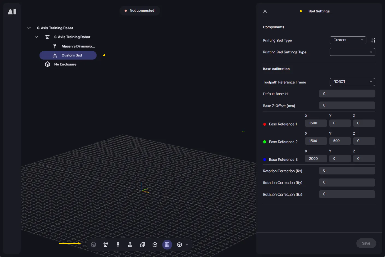
Aibuild Release 3.4.64 + your new AI engineer

16 January 2026

Today's major release introduces a huge array of tools to create, inspect, diagnose, and improve toolpaths before you print. The update includes an AI agent and makes printer configuration easier with a new component tree and includes a series of improvements to toolpathing, operators, weaving, performance and more.

Introducing our new AI Agent.

Our AI Agent is built into Aibuild to help you move faster day-to-day: it can explain what you’re seeing in Aibuild, answer questions about operators and settings, suggest better slicing and toolpath strategies, and help you build workflows. It’s also integrated into the Postprocessor Editor so you can adjust how your program files are generated and exported without needing to write Python code.

For toolpathing

Use the agent in the Workflow Editor when you need a quick explanation of a workflow, operator settings, or slicing choices. It’s useful for sanity-checking decisions (e.g. slice mode, overlap, infill strategy) and reducing trial-and-error when iterating on real parts.

If you ask, the AI Agent can add operators to your workflow and suggest settings based on our 10+ years in LFAM, helping you build efficient toolpaths and achieve consistent print quality.


For writing post-processors

Use the agent inside the Printers Page → Custom Postprocessor → Code Editor page to draft or modify postprocessor logic based on your target machine language and example toolpath files. You can upload sample files, ask for changes, and have the agent apply updates directly in the editor, with a built-in comparison step before changes are applied.

How to open the AI Agent

Open the AI Agent from the Workflow Editor operator toolbar by clicking the ✨ icon. Starting a new chat shows suggested prompts to help you get going. You can revisit old threads from Chat History in the “…” menu.


Rollout note: We’re rolling out the AI Agent gradually due to current service capacity limits, so it may not appear for all users immediately. All users will have access by the end of the week.

Postprocessor code and toolpaths still needs engineering judgement — review the generated output and validate it against your machine and process before running on hardware.

How to inspect polylines in the 3D view.

You can now hover and click individual polylines in the 3D scene to inspect exactly what you’re looking at. Hover to highlight a line, then click to lock the selection and show key properties (such as layer and line type) in a small overlay in the top-left.

The information adapts to the active visualisation mode (for example sequence, layer number, or thickness), making it easier to pinpoint specific segments during toolpathing. This also works with Quality Checks, so you can inspect and diagnose flagged segments the same way.

Quickly see setting diagrams.

We’ve added nearly 200 setting diagrams so you can see, at a glance, what a specific setting will do to your toolpath. In the Workflow Editor, hover over a setting name to get a short explanation plus a visual. It’s a faster way to understand advanced settings in operators like Slice, Optimise, Brim, RebuildPolylines and Infill2D and make confident changes without trial-and-error.

New printer configuration page.

New component tree

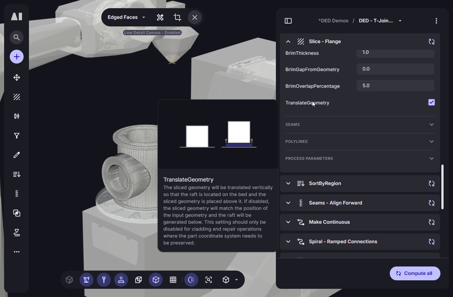
The Printers page has been reorganised around a component tree so you can configure your system the same way you think about it: machine, tool, bed, enclosure (and related components).

Select a component in the tree to focus it in the scene and see only the settings that matter for that component, instead of digging through one long list. This makes it quicker to set up a new printer, and much easier to find and adjust the right settings when iterating on an existing system.


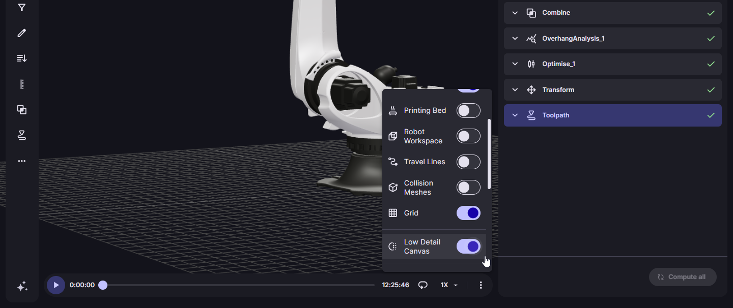
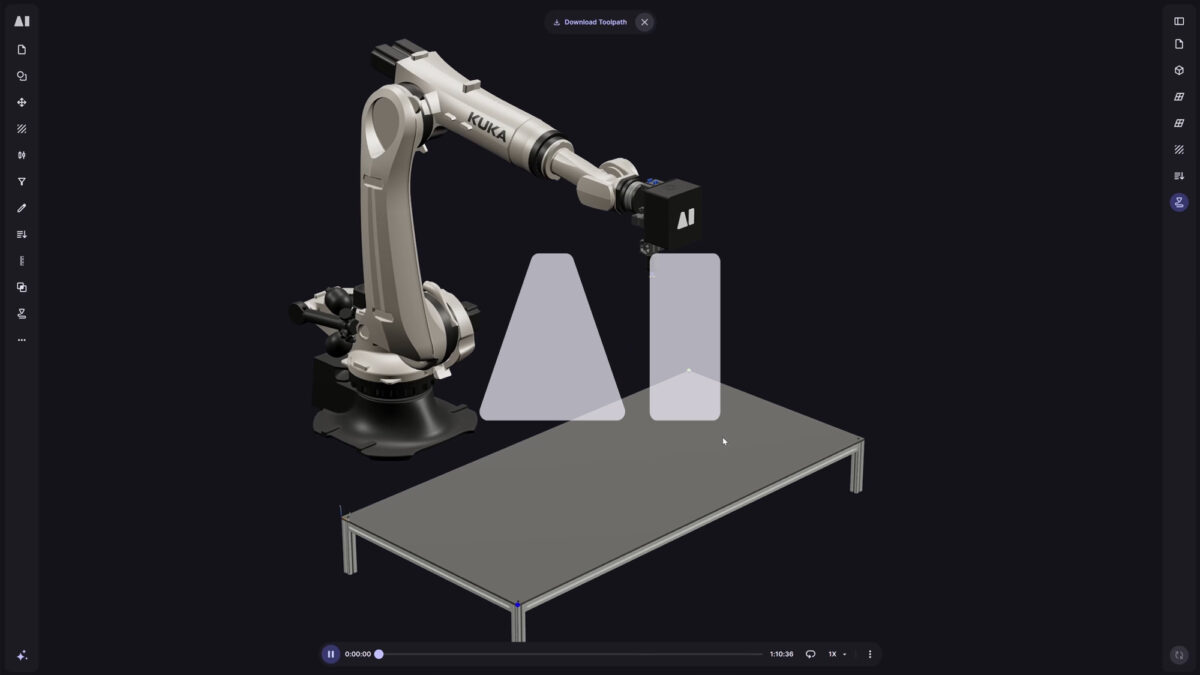
Printers visibility controls

The Printers page bottom toolbar now lets you show/hide the tool independently from the machine and toggle collision meshes just like in the Workflow Editor. This makes it easier to inspect your setup: isolate the tool when checking clearances or mounting, and switch between printer models, collision meshes, or both when validating collision geometry.


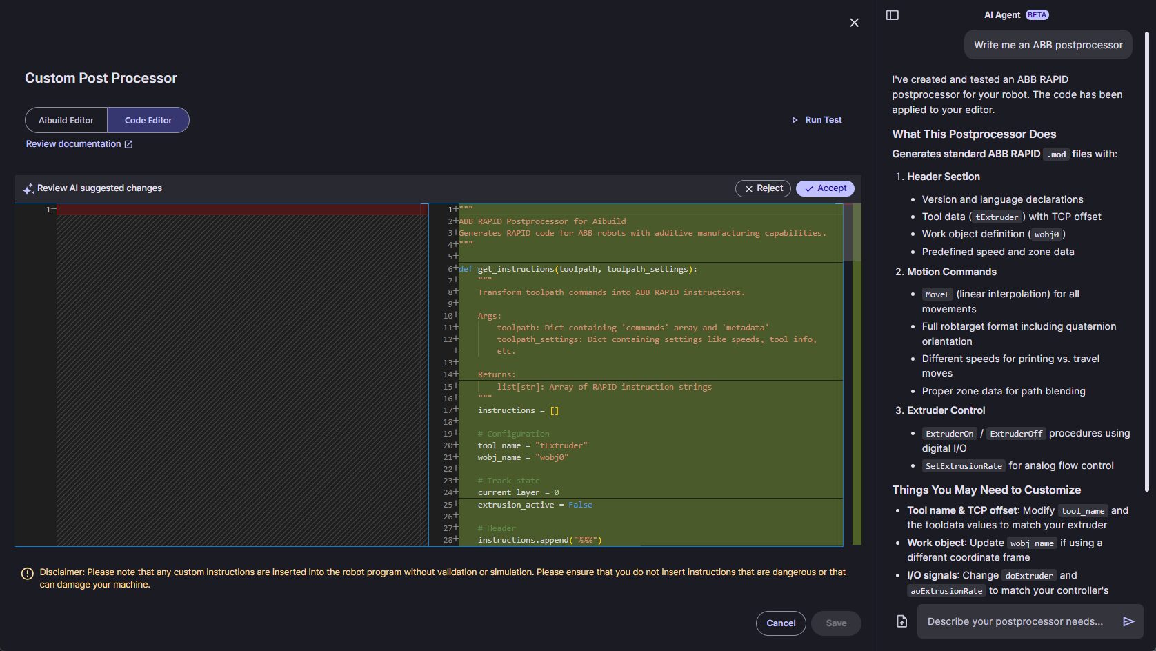
Documentation for Code Editor

The Postprocessor Code Editor now includes a View Documentation link that opens a new tab with up-to-date documentation for the postprocessor and available toolpath/settings data. This makes it much easier to understand what fields you can read and write when building custom machine logic.

Toolpathing.

Assign process parameters per segment (for metal AM)

You can now assign different job/process parameter IDs to sections within a single polyline, instead of being forced to apply one ID to the entire polyline. This makes it much easier to tune parameters for specific regions (for example bridges, junctions, weaves, overhang zones) without splitting polylines and risking sequencing side-effects. Configure it in the Edit operator by filtering/selecting the segments you want, then setting the Process Parameter ID (also known as Job ID) for just those segments.

Weaving

  • Now available for Radial slicing – Weaving is now available as an infill pattern in Radial slicing mode, so you can generate continuous ‘back-and-forth’ toolpaths for radially-symmetric geometries. The seam behaviour has been improved so the weaving pattern aligns more reliably when the toolpath completes a full layer region.
  • More reliable in thin or narrowing regions – Fixed glitches when weaving passes through regions that pinch or shrink mid-path by splitting thin sections and joining results back cleanly. This improves continuity and avoids malformed weaving in tight features. Weaving infill is also now disabled when Single Line Extrusion mode is enabled.
  • Improved path quality on thin and complex regions – Weaving infill is now more stable on parts with tight features (like thin trailing edges), reducing trimmed paths and underfilled areas that could show up as gaps. The pattern generation has been adjusted to better respect the effective bead width/overlap when simplifying and trimming boundaries, resulting in cleaner, more complete weaving across layers.
  • More reliable first/last line connections – Fixed an issue where the first and last weaving connections could be incorrect when lines were trimmed, improving continuity at the start/end of weaving regions and reducing small gaps.
  • Cleaner endings on boundary – Improved how weaving finishes at region ends so the final segments follow the boundary more consistently and keep the boundary segment in place. This reduces odd end patterns and makes weaving density more predictable near terminations.
  • Seams now follow the boundary seam – Fixed an issue where weaving seams could appear in random locations and ignore seam rules. Weaving infill now aligns its seam more closely to the boundary seam in Infill2D and Slice, giving more consistent seam placement and cleaner surface results.
  • Smoother paths to reduce over/under extrusion – Weaving polylines are now smoothed automatically to avoid sharp, “centreline-following” wiggles that can cause local over- and under-extrusion. This produces a more consistent weave in curved regions without requiring manual tuning.

Infills

  • Improved start position: Zigzag infill now starts from a more consistent point on the part, reducing “random-looking” gaps and making the pattern easier to predict, especially when iterating on infill angle and density.
  • Control where continuous connections are placed: When using RECTANGULAR_LINES with Make Continuous enabled, you now have better control over how connections are created between neighbouring infill regions. A new ConnectionLocation setting lets you choose: * Random – vary connection points to reduce visible alignment artefacts. * Aligned – keep connection points consistent across layers/regions for a cleaner, more uniform result.
  • Connection Shift setting visibility fix – Fixed an issue where the Connection Shift control could be missing for Rectangular Lines with Aligned connections, so you can reliably fine-tune where connections land.


Performance

  • You can now set Low Detail Mode to be enabled by default via Settings > Preference. This helps if you regularly work on large toolpaths or heavy scenes and want faster rendering without toggling it on every session. You can turn it off at any point from the 3D scene’s bottom toolbar.
  • The Low Detail Mode button is now available even when no operator output is selected, and it’s also shown when the Toolpath operator is selected. This makes it quicker to boost FPS during toolpath simulation without needing to click into another operator first.

Milling

  • Smoother toolpaths from OBJ/STL stock – Improved milling polyline resolution when using OBJ or STL stock models as input, reducing coarse “stepped” corner offsets and producing cleaner, smoother milling toolpaths.
  • Pocket Clearing pass generation fixed – Fixed an issue where Pocket Clearing could fail to generate multiple passes for certain selected surfaces, improving reliability on complex parts.


Radial Slicing

  • Fix: Supports elevated geometry – Fixed an issue where Radial slicing could error if the part wasn’t sitting on the bed, making it more reliable when working with lifted or pre-positioned geometry.
  • Fix: Closed polylines now stay closed – Fixed a bug where Radial mode could generate open polylines even with Close open polylines enabled, improving continuity and downstream toolpath reliability.


Other Operators

  • Orient tool to previous layer now behaves correctly with filtering – Fixed an issue in the Edit operator where Orient tool to previous layer could produce incorrect rotations when used alongside analysis-based filtering. Orientation is now calculated consistently, and only the intended (filtered) segments are affected.
  • Filter Segments error fixed – Fixed an issue in the Edit operator where enabling ‘Filter Segments’ in the Edit operator could throw an error when filtering by analysis data. Filtering now works reliably across edits like tool rotations, layer height, line thickness, and speed multipliers, so you can target only the segments you want to adjust.
  • Join polylines now off by default – In Spiral slicing, ‘Join polylines’ is now disabled by default to avoid accidentally merging layers into a single continuous path. This prevents issues like removing layer-time wait logic, while still letting expert users enable it intentionally where it’s needed.
  • Preserve process parameter IDs when joining polylines – Fixed an issue where using Join Polylines could change segment process parameter IDs, which could break fine-tuned parameter control across a path. Joined polylines now keep their original segment IDs so your downstream postprocessing and parameter mapping behave as expected.


Thermal Simulation

  • Base plate now snaps to the mesh bottom – Fixed an issue in ‘Create Finite Element Mesh’ where the base plate could sit above/below the FE mesh instead of aligning to its lowest surface, which could throw off the thermal setup (especially when first-layer offsets were used).
  • Added check for non-continuous meshes – The Create Finite Element Mesh operator now checks the FE mesh is a single connected body and shows an error if it’s split into multiple disconnected parts, preventing invalid simulations.


Collision Detection

  • Improved accuracy for Comau robots – Fixed an issue for Comau robot types where collision models could move inaccurately during simulation. Collision checks are now more reliable for this robot type, improving confidence in safety checks before exporting toolpaths.
  • Reach Limits highlighting restored – Fixed an issue where unreachable polylines were no longer highlighted red in the physical simulation, even though Reach Limits were being detected. Unreachable segments are now shown correctly again, making it easier to spot and fix reach problems before export.
  • Collision highlighting restored – Fixed an issue where collisions were reported in the Safety Checks panel but the affected polylines weren’t highlighted red in the simulation. Colliding paths are now shown correctly again for fast diagnosis.
  • Expanded collision models for more 6-axis robots – We’ve added collision models for more robot types in the printer library, so you can run robot-based collision detection checks when your LFAM printer is using one of these robot models. If you’re using a different robot, you can still add your own collision model via a custom robot on the Printers page.

Solid Bead View

  • Fix: Solid polyline (bead) visualisation: consistent end caps – Fixed a rendering issue where the start of a solid polyline could appear sharp while the end looked rounded, creating a misleading “gap” when inspecting bead geometry. Solid polylines now render consistently so toolpath inspection matches the actual output.


BREP surface selection

  • Fix: BREP surface selection after duplicating a workflow – Fixed an issue in duplicated workflows where interactive BREP surface selections (for example in Slice) could error after duplicating a workflow and then editing the selection. Duplicated workflows now keep surface selection inputs stable so you can continue refining them normally.


Toolpath Weight

  • Fix: custom material weight shown correctly in simulation – Fixed an issue where parts using custom materials could show an incorrect or missing weight in the simulation/toolpath view due to how material density was being parsed. Weight estimates now update correctly when you change material density or switch between materials.


Travel Moves

  • Jumps: higher limit for jump in/out moves – Increased the maximum supported jump in/out distance to 500, helping with larger parts where longer retract/approach moves are needed.
  • Fix: travel moves no longer inherit the next feature’s line type – Fixed an issue where some non-printing travel moves (for example JUMP_OUT moves when using follow printed path) could be tagged with the next feature’s line type (like wall or infill) instead of TRAVEL. This makes toolpath classification more reliable for postprocessors that use line type to generate machine code.