Aibuild Release 3.4.81

4 February 2026

Today’s release follows hot on the heels of the last: by vastly expanding the AI Agent's capabilities with iterative feedback loops and toolpath quality reasoning.

It also introduces new analysis tools to catch dimensional defects and high acceleration before printing, and it brings a world-first: nonplanar weaving for 6-axis DED.

Ai Agent

Use Quality and Safety Checks for Reasoning

The AI Agent now understands toolpath quality checks and safety analysis results.

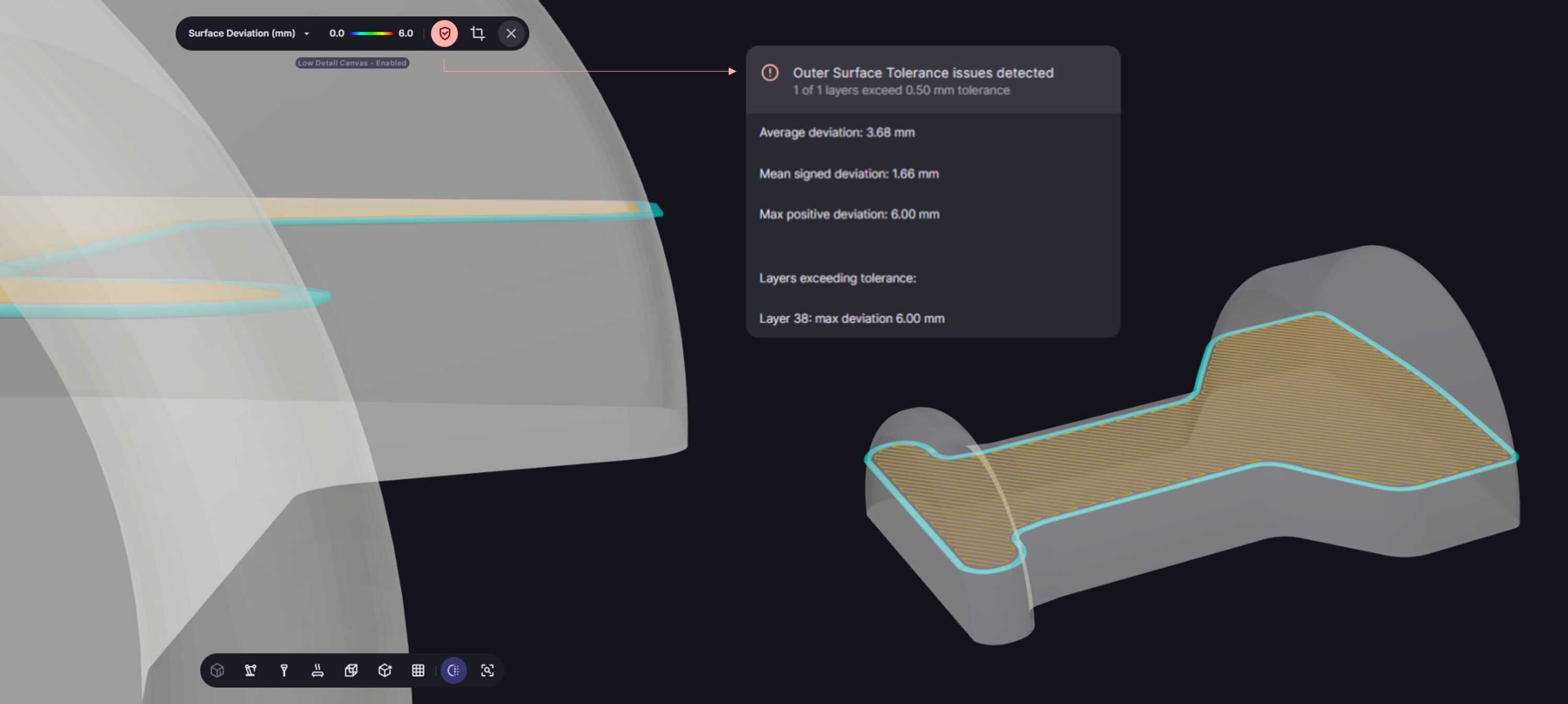
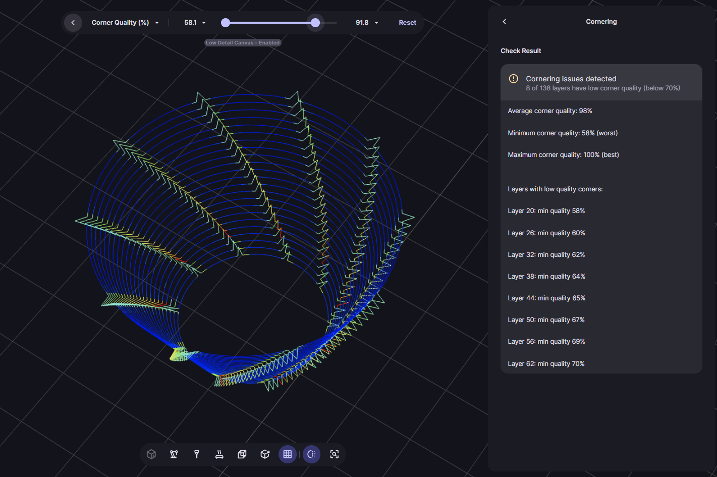
After computing a toolpath, the AI Agent can now read and interpret results from **quality checks** (”measures of quality for a toolpath”) and **safety checks** (”unreachable areas and collision risks”). This lets you ask questions like “Is this toolpath good?”, “Where are the problem areas?”, or “Does my toolpath have collisions?” and get informed answers with specific feedback on print quality and suggested improvements to fix or optimize your toolpath.

Use to:

  • Ask the agent to evaluate toolpath quality and get specific feedback on issues
  • Identify problem areas automatically without manually reviewing check results
  • Get context-aware suggestions for toolpath improvements based on detected issues

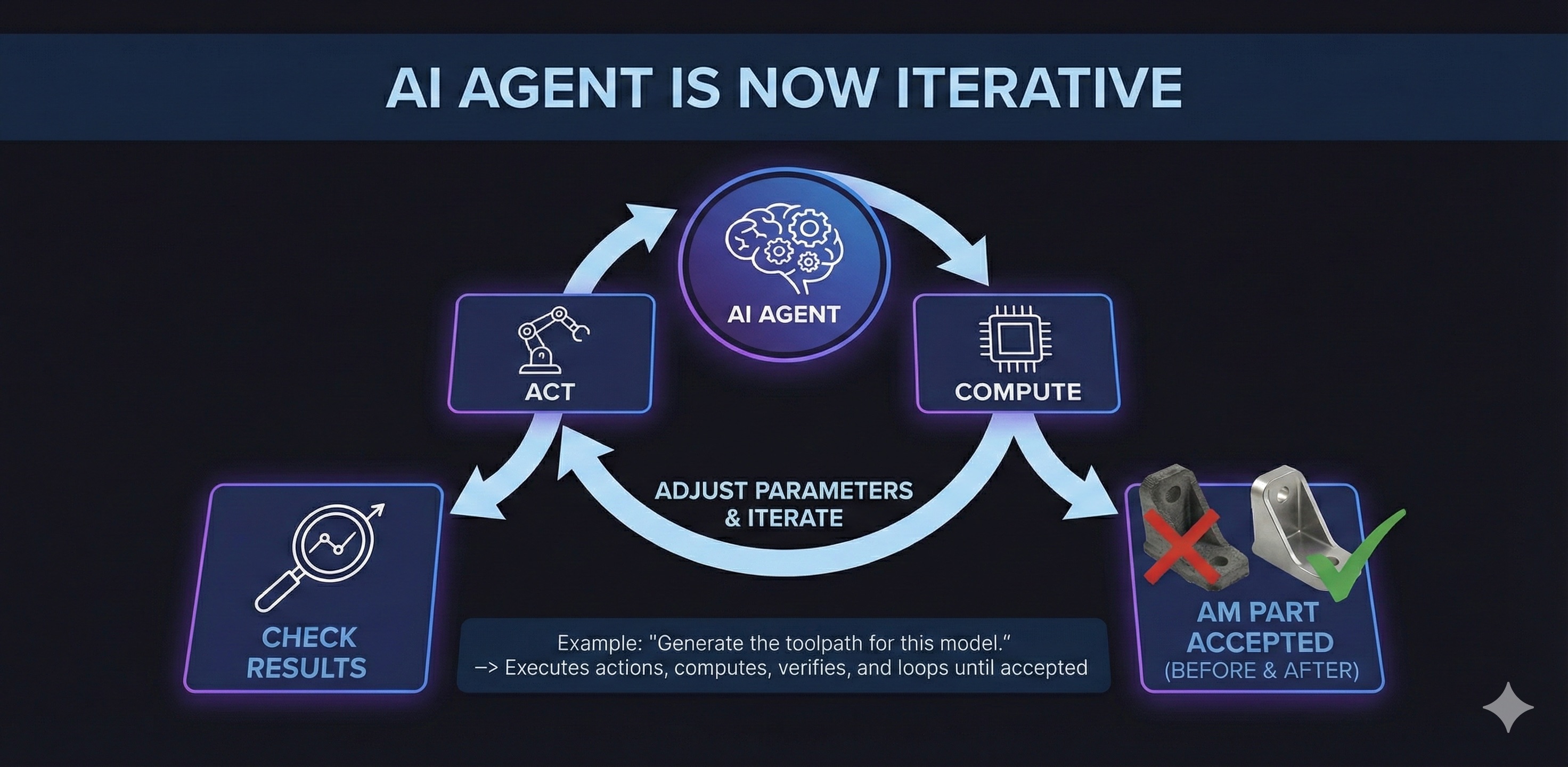
AI Agent Is Now Iterative.

The AI Agent can now loop and work autonomously through multi-step actions.

Act → Compute → Check results → Act again.

The AI Agent can now execute a feedback loop from a single prompt like “Generate the toolpath for this model.” It performs actions, computes results, checks outputs, and iterates back to adjust settings until the final result is accepted by the agent.

How it works:

The agent uses a loop-and-verify approach: it executes an action, computes the result, evaluates whether the outcome meets requirements, and if not, adjusts parameters and tries again. This continues until the workflow reaches an acceptable state or the agent determines no further improvement is possible. Give the agent criteria for optimization to guide its choices.

Use to:

  • Generate complete, optimised toolpaths from a single instruction: “Create a good toolpath for this part”
  • Explore parameter variations automatically: “If I adjust the bead position, how does this affect my toolpath?”
  • Resolve issues autonomously: “Can you edit the tool rotations until there are no longer any collisions?”
  • Compare toolpath approaches: “If I print this with a different slicing angle, how does it affect my print time and part quality?”

Other AI Agent Improvements.

  • Panel Opens Automatically – The AI Agent panel now opens by default the first time you open a workflow, making it more discoverable. If you close the panel, it will remember your preference per workflow.
  • Fix: Input Focus Jumping – Typing in numeric setting fields in an operator no longer causes focus to jump immediately to the AI Agent chat box.
  • Fix: Panel Collapse Bug – The workflow editor panel now collapses properly without leaving clickable operator areas at the screen edge.
  • Fix: Panel Border Alignment – Corrected visual alignment of the AI Agent panel borders.

Quality checks.

New Check: Surface Tolerance

Compares your toolpath against the target mesh to verify dimensional accuracy.*

Parts that deviate too far from the target mesh can fail tolerance requirements or require excessive machining to bring them into spec.

What it does:

This check compares your toolpath’s outer surface against the input mesh and generates a heatmap showing where the printed part will be oversized or undersized. You define the maximum acceptable deviation (in mm), and the check flags layers that exceed this tolerance.

How it works:

The analysis automatically identifies which polylines represent the outer surface—outer walls where they exist, or infill segments where they’re exposed—giving you an accurate picture regardless of your slicing strategy. The input mesh is overlaid in the 3D view for easy visual comparison, and the check reports maximum and average deviation across the part.

Use to:

  • Verify that critical dimensions meet tolerance requirements before committing to a print
  • Plan stock allowance for post-machining operations – knowing exactly how much material needs removing helps you calculate milling passes and machining costs
  • Compare different toolpath modes, offsets, and settings to find the optimal approach for your target part – optimise based on dimensions rather than guesswork
  • Decide whether to print faster with more stock for machining, or slower with tighter tolerances to eliminate finishing steps entirely

New Check: Cornering Acceleration.

Identifies sharp turns at high speeds that can cause print defects.

Toolpaths with sharp turns at high speeds can cause print quality issues like ringing in polymers, bead inconsistencies in metals, or flow disruptions in concrete.

What it does:

This check calculates a cornering severity score based on the physics of each turn (centripetal acceleration), combining feedrate, corner angle, and segment length. Each corner gets a quality score from 0–100%, where 100 is smooth and 0 indicates a problematic corner that may exceed your machine’s acceleration limits.

How it works:

The tool will flag any layers that exceed a severity threshold, and visualises the problem areas in the 3D scene so you can identify and fix aggressive cornering before printing.

Use to:

  • Identify aggressive cornering before printing, avoiding defects
  • Compare different toolpath strategies to find smoother motion profiles
  • Tune speed settings to stay within your machine’s acceleration capabilities

Other Quality Check Improvements.

Zoom Extents Button – Added a “Center Object on screen” button to the Quality Checks interface that automatically zooms and centres the camera on your toolpath, making it faster to inspect flagged issues without manually adjusting the 3D view.

Overhang Analysis Text Fix – Fixed an unnecessary character (Â) that appeared in the overhang analysis results, making layer-by-layer reports cleaner and easier to read.

Nonplanar Weaving Strategy (Beta)

World-first nonplanar weaving toolpaths for 6-axis DED and WAAM systems.

In metal additive manufacturing (DED, WAAM, laser wire), weaving or meandering toolpaths—where the torch oscillates back and forth as it deposits material—enable wider wall structures, improve heat distribution across the deposition area, and achieve better dimensional accuracy on curved surfaces. Until now, weaving has been limited to planar deposition strategies.

This release brings Aibuild’s leading nonplanar toolpath technology to metal AM, enabling weaving strategies on curved, non-planar surfaces for the first time on robotic 6-axis systems.

How it works:

The Nonplanar slicing mode now supports weaving infill across all nonplanar strategies. To enable, turn on infill and select weaving. The system unwraps suitable guide meshes (those with a single naked edge), generates the weaving pattern in 2D to maintain accurate bead spacing, then maps the pattern back to the 3D surface.

Use for:

  • Manufacturing components with varying wall thicknesses – Build parts that require thicker walls in specific areas without changing process parameters or making multiple passes.
  • Better heat distribution on complex geometries – Distribute heat over a wider area rather than concentrating it in a single spot, reducing thermal distortion and achieving more consistent bead geometry on curved surfaces.
  • Improved dimensional accuracy for curved parts –-Achieve better formability and surface quality when depositing on non-planar surfaces where gravity affects the melt pool
  • Cladding and coatings on curved surfaces – Apply protective or functional coatings to continuously varying geometries without sacrificing the process stability benefits of weaving.
  • Complex geometry repair – Repair worn turbine blades, moulds, or other components with non-planar damage profiles while maintaining dimensional accuracy
  • Pre-visualisation and optimisation – View and optimise your weaving toolpath before manufacturing, rather than relying on robot controller auto-weaving that you can’t inspect in advance

This is a world-first capability for 6-axis DED systems and represents a significant advancement in nonplanar metal additive manufacturing.

Combine Operator, New Mode: ALTERNATE.

The Combine operator can now alternate between inputs rather than sequencing them all at once.

A new Mode setting lets you choose how the Combine operator merges multiple path inputs. The default behaviour (Sequence Data) processes all polylines from the first input, then all from the second input, and so on. The new Alternate Data mode switches between inputs on a per-layer basis, processing one layer from the first input, then one from the second, and repeating. This makes it possible to weave together paths from separate sliced parts or different processing strategies.

Use for:

  • Building multiple parts simultaneously with layer-by-layer alternation to manage heat distribution
  • Interweave different material depositions or process strategies within a single build
  • Creating hybrid structures where different sections use different toolpath approaches

Setting Diagrams.

Additional operators now include visual diagrams when you hover over settings, making it easier to understand how they affect your toolpath. The Mould Designer, Rebuild Polylines, Curvature Compensation, Split Polylines, Optimise, and Overhang Analysis operators now have diagram support alongside the ~200 diagrams added in the previous release for Slice, Infill2D, Brim, and other operators.

Operators.

Improvements to various operators in the Workflow Editor.

Weaving

  • Increased pattern overlap limit – The Pattern Overlap Percentage for weaving patterns can now be set up to 200%, giving more control over bead spacing in wide weaving applications.
  • Simplified weaving settings – Removed the Infill Wall Overlap Percentage setting from weaving since weaving uses its own offset control, reducing redundant settings.

Radial Slicing

  • Improved polyline quality on angled surfaces – Fixed jittering and wavy polylines that occurred when the slicing cylinder guide was parallel to the mesh surface, producing smoother, more consistent circular paths. Users will note this improves path quality especially in radial.
  • Fixed Infill Wall Overlap Percentage – The Infill Wall Overlap Percentage setting now correctly affects the output in Radial slicing mode.
  • Added Bed Centre option for slicing centre – You can now automatically use the bed centre as the slicing centre point for radial slicing, removing the need to manually create and position a reference point with the CreatePoint operator.

Cladding

  • New seam settings for zigzag infill – Added seam control settings (Clockwise, Counter-clockwise, Alternate Direction) to Cladding mode, giving you control over the starting point and direction of zigzag infill patterns. This helps avoid geometry irregularities at start/stop points that can accumulate across layers and affect dimensional accuracy.

Multiplanar

  • Fixed layer height issues – Resolved problems with fixed layer height in Multiplanar mode where brim was incorrectly generated at each section and missing layers appeared with open polylines.

Mouse Selection

  • Cleaner polylines from BREP and mesh models – Fixed occasionally irregular, jagged polylines when using mouse selection on BREP surfaces or mesh models by adding a cleaning up step for tiny segments before offsetting, resulting in smoother walls.

Bead Offset

  • Improved internal offsetting – Fixed bad polylines caused by internal offsetting in the Slice operator (Bead Offset setting) by removing very short segments before offset calculations, eliminating glitches in outer walls. This clean up step is linked to the mouse selection fix.

Edit Operator

  • Fixed process parameter ID assignment for segments – Corrected an issue where assigning process parameter IDs (PP ID) to polylines with an Edit operator applied changes to the entire polyline instead of individual segments. It now allows proper segment-level parameter control.